FPGA 3D Graphics Engine
The goal of this project was to have a Linux userspace application interact with a GPU character device (/dev/gpu0), where the GPU is implemented an FPGA and is able to render and manipulate 3D objects. The GPU shares a common bus with other peripherals on the FPGA.
To keep things simple, the 3D objects are specified in specified in the Wavefront .obj file format.
Results
The final renders below are produced in 3 different ways:
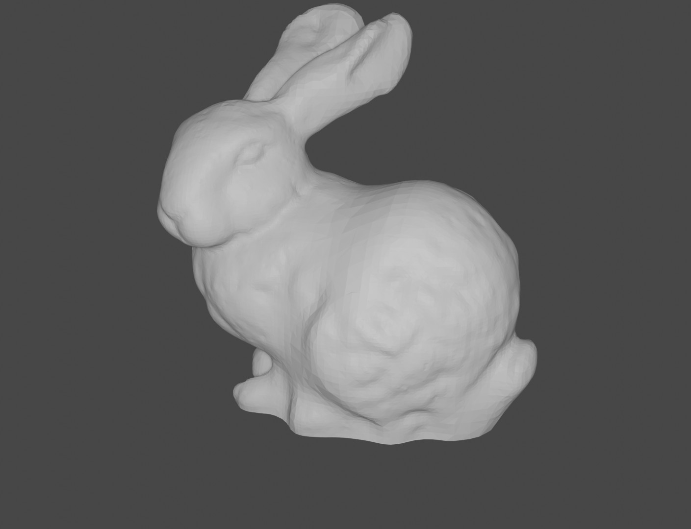
- There is the OpenGL application that acts as a reference for hardware development (OpenGL is only used to draw pixels on a GUI application. None of the high level rendering APIs are used).
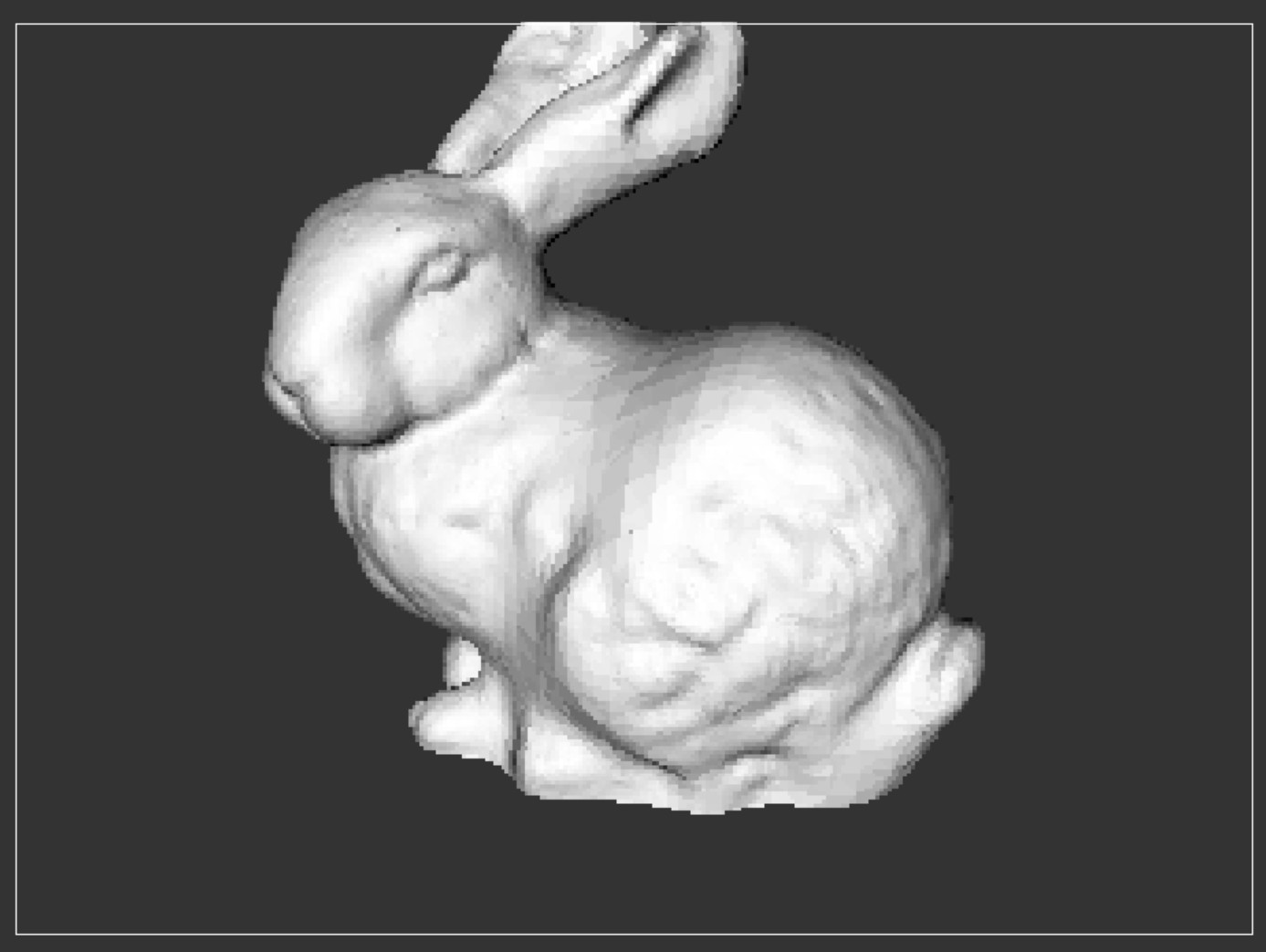
- There is also a pure software rendering program built for the ARM A9 Linux environment on the DE1-SoC. This program calculates pixel data on the CPU and writes it out to a VGA controller framebuffer. The performance of this program will be used as a baseline for “software rendering.”
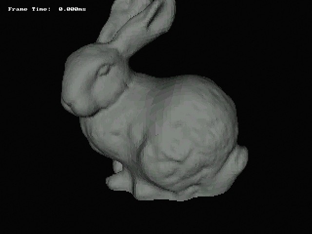
- The final program is the Linux userspace “app” that makes use of the completed GPU and Linux driver to perform rendering. It just has to load the 3D object into memory and hands off the rendering to the GPU.
Performance
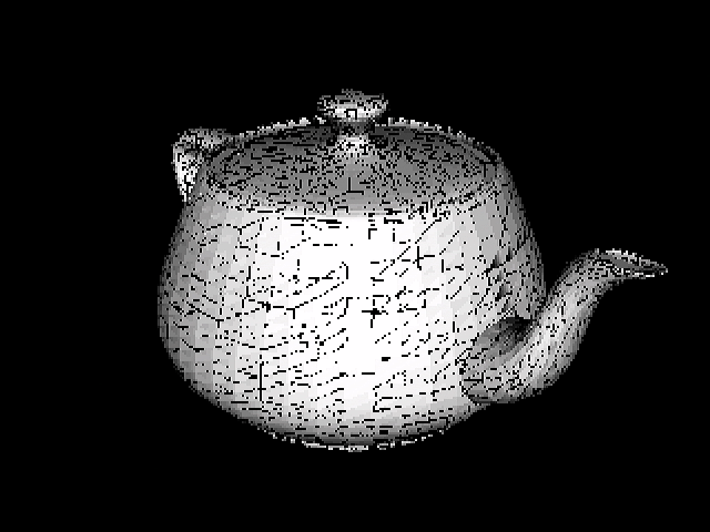
The reference OpenGL implementation achieves an average frame-time of 10ms when rendering the Utah Teapot on an i7 6700HQ. The ARM A9 on the DE1 achieves an average frame-time of 280ms (running under Linux). The FPGA GPU took 882us to render the same image.
| ARM A9 | FPGA GPU | |
|---|---|---|
| Frame-Time (ms) | 280 | 0.9 |
| Triangles | 9438 | |
The GPU result is maybe not as impressive as it initially seems. As will be seen in the architecture section, the GPU makes heavy use of data parallelism and pipelining whereas the SW based programs are largely serial and unoptimized (as they were mostly used as references for HW), so I’m sure the gap between them could be reduced.
Visual Differences
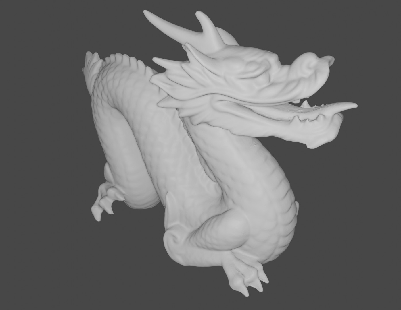
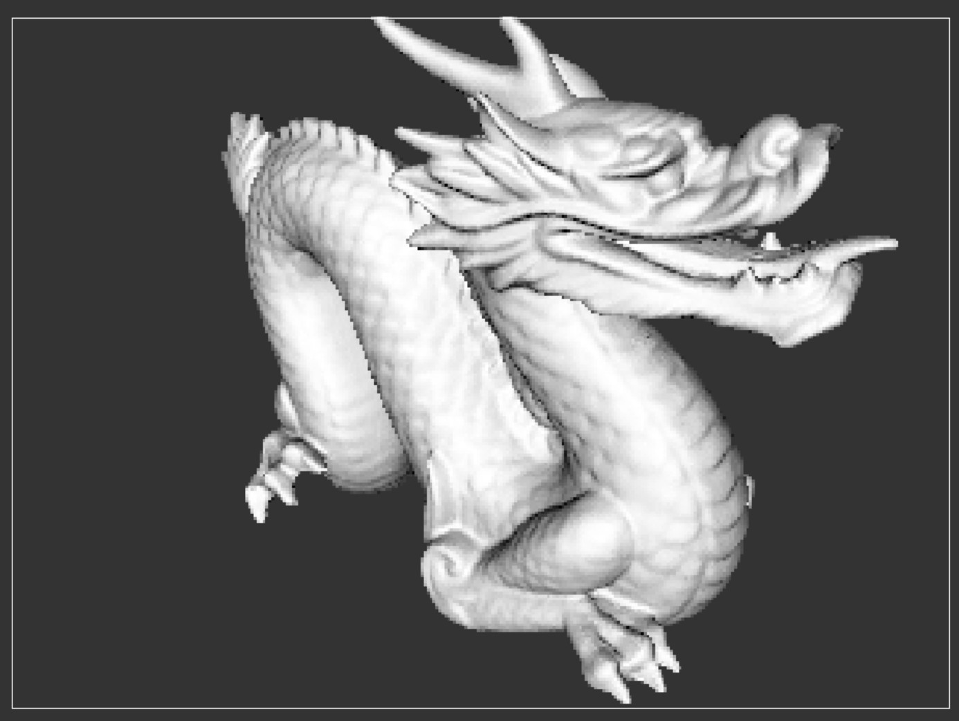
The three rendering techniques produce mostly similar visual results.
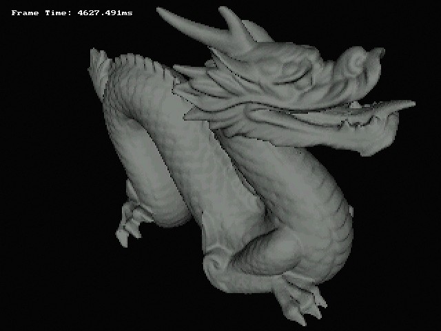
Most notably, the GPU version of the image has a lot of black pixels that should be coloured. This is possibly Z-Fighting caused by limited precision in the Z-buffer (a consequence of synthesis constraints), or by limited precision elsewhere in the pipeline (most likely the Intel Divider IP blocks). These two areas are the places that differ the most from the float32 reference program.
When I switch the OpenGL reference to use fixed Q13.14 format, the black pixels appear there too. Using a more precise format like Q16.16 mostly resolves the issue, but this format cannot be synthesized onto the FPGA. The DSP blocks on the Cyclone V FPGA natively support 27bit wide operands (Q13.14). Using more than 27bits on a operand consumes more than 1 DSP block per Verilog multiplier instantiation, so the design will not fit onto the FPGA.
The difference in background colour between DE1-SoC VGA and OpenGL is because there isn’t an easy way to set the background colour on the VGA Subsystem. It would require a traversal of the entire framebuffer.
The VGA Subsystem also uses a more limited 16bit colour scheme compared to OpenGL.
System Architecture

GPU Architecture

A possible future improvement would be to use an instruction fetching command processor based architecture on the GPU frontend in addition to the control/status registers as this would have simplified the HW-SW coordination required for drawing multiple frames back-to-back.
Another future improvement would also be switch out the Intel IP for generic RTL (dividers, FIFOs, MACC units) in order to make the design vendor agnostic, but synthesis quality would most likely take a hit here.
Synthesis Results
+--------------------------------------------------------------------------------------+
; Flow Summary                                                                         ;
+---------------------------------+----------------------------------------------------+
; Flow Status                     ; Successful                                         ;
; Revision Name                   ; DE1_SoC_Computer                                   ;
; Top-level Entity Name           ; DE1_SoC_Computer                                   ;
; Family                          ; Cyclone V                                          ;
; Device                          ; 5CSEMA5F31C6                                       ;
; Timing Models                   ; Final                                              ;
; Logic utilization (in ALMs)     ; 19,492 / 32,070 ( 61 % )                           ;
; Total registers                 ; 29149                                              ;
; Total pins                      ; 368 / 457 ( 81 % )                                 ;
; Total virtual pins              ; 0                                                  ;
; Total block memory bits         ; 1,819,077 / 4,065,280 ( 45 % )                     ;
; Total DSP Blocks                ; 56 / 87 ( 64 % )                                   ;
; Total HSSI RX PCSs              ; 0                                                  ;
; Total HSSI PMA RX Deserializers ; 0                                                  ;
; Total HSSI TX PCSs              ; 0                                                  ;
; Total HSSI PMA TX Serializers   ; 0                                                  ;
; Total PLLs                      ; 2 / 6 ( 33 % )                                     ;
; Total DLLs                      ; 1 / 4 ( 25 % )                                     ;
+---------------------------------+----------------------------------------------------+
+-----------------------------------------------------------------------------------------------------------------------------+
; Slow 1100mV 85C Model Fmax Summary                                                                                          ;
+-------------+-----------------+--------------------------------------------------------------------------------------+------+
; Fmax        ; Restricted Fmax ; Clock Name                                                                           ; Note ;
+-------------+-----------------+--------------------------------------------------------------------------------------+------+
; 62.74 MHz   ; 62.74 MHz       ; altera_reserved_tck                                                                  ;      ;
; 71.32 MHz   ; 71.32 MHz       ; The_System|system_pll|sys_pll|altera_pll_i|general[0].gpll~PLL_OUTPUT_COUNTER|divclk ;      ;
; 167.93 MHz  ; 167.93 MHz      ; The_System|video_pll|video_pll|altera_pll_i|general[1].gpll~PLL_OUTPUT_COUNTER|divclk;      ;
+-------------+-----------------+--------------------------------------------------------------------------------------+------+
system_pll clock output was therefore configured to be 50MHz, and this drove the FPGA GPU, as well as the interconnect and all other peripherals (other than the Video PLL).
The critical path was along the DSP enabled Intel Divider IP blocks, so there wasn’t a lot of room for improvement here. The IP wizard allows you to select the number of pipeline stages, but even with them set to 20, the Fmax stopped improving.
Additional Rendered Objects
Stanford Bunny
Stanford Dragon
For guidance on understanding the 3D Graphics pipeline, I used the following sources:
GPU RTL Progress
- Avalon Interfaces
- Command Stream Avalon MM Slave
- Vertex Fetch Avalon Master
- Raster Backend Avalon Master
- Vertex Processor
- Vertex Transform
- Vertex Shader
- Rasterization Engine
- Triangle Setup
- Bounding Box Function
- Edge Function & Half Plane Test
- Depth Test & Z Buffer
- Linux Kernel Module